TM-9-2350-256-10 - Page 48 of 796
FIXED FIRE EXTINGUISHER SYSTEM (FFES), IF EQUIPPED
•
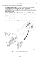
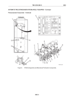
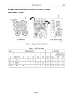
Dual Pull Mechanism (Figure 6, Item 1)
— connects the two sets of remote control pull handles
(Figure 6, Items 3 and 6) to the cylinder control valves (Figure 6, Item 4) via cables.
•
Engine Shutoff Switch (Figure 6, Item 2)
— closes the fuel shutoff solenoid valve in the fuel system
when the interior remote control pull handle (Figure 6, Item 3) shield is released. This action shuts down
the main engine if it is running.
•
Interior Remote Control Pull Handles (Figure 6, Item 3)
— discharge the FFES when pulled.
•
Cylinder Control Valve (Figure 6, Item 4)
— controls the discharging of the cylinder banks. The cylinder
control valves are operated by the remote control pull handles (Figure 6, Items 3 and 6) or manually by
pushing the lever.
•C
O
2
Cylinder (Figure 6, Item 5)
— eight 10-lb (4.5-kg) cylinders are located in two banks of four
cylinders each on the left and right sides of the crew compartment. Each bank is connected to a cylinder
control valve (Figure 6, Item 4).
•
Exterior Remote Control Pull Handles (Figure 6, Item 6)
— discharge the FFES when pulled.
Figure 6.
Fixed Fire Extinguisher System (FFES).
TM 9-2350-256-10
0003
0003-6
Back to Top

