TM-9-2350-256-10 - Page 44 of 796
CHARGING/STARTING SYSTEM AND VEHICLE BATTERIES - Continued
•
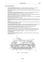
Neutral Safety Switch
— mounted on the brake assembly, functions as a safety switch to prevent
starting the engine while the transmission shift control is in any shift position other than Park (P).
•
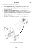
Master Relay
— located in the left rear of the engine compartment. It controls primary power to all
electrical systems and components with the exceptions of the personnel heater system, the MASTER
switch, and the slave receptacle.
•
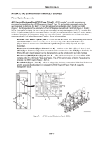
Batteries
— six 12-V batteries are connected in a series-parallel circuit to give the vehicle a 300-A/hr
source of 24 Vdc power. The batteries are located in the left side of the engine compartment.
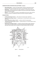
COOLING SYSTEM
•
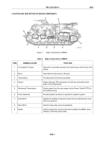
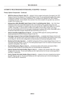
Air Intake Grilles (Figure 2, Item 1)
— allow cooling air to enter the engine compartment.
•
Engine Oil Coolers (Figure 2, Item 2)
— circulate engine oil. Air flows through the coolers to remove
excess heat.
•
Exhaust Deflector Doors (Figure 2, Item 3)
— provide an outlet for the exhaust system.
•
Transmission Oil Coolers (Figure 2, Item 4)
— circulate transmission oil. Air flows through the coolers
to remove excess heat.
•
Engine-driven Fans (Figure 2, Item 5)
— circulate the cooling air through the engine compartment.
They are driven by the engine through an oil-cooled clutch assembly that is designed to slip under
deep-water fording conditions where the resistance of the water exceeds the friction of the clutch.
Figure 2.
Cooling System.
TM 9-2350-256-10
0003
0003-2
Back to Top

