TM-9-2350-256-10 - Page 49 of 796
AUTOMATIC FIRE EXTINGUISHER SYSTEM (AFES), IF EQUIPPED
Primary System Components
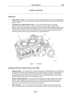
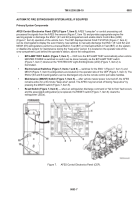
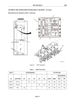
AFES Control Electronics Panel (CEP) (Figure 7, Item 3).
AFES "computer" or control processing unit
processes fire signals from the AFES fire sensors (Figure 7, Item 10) and provides appropriate engine fire
warning signals to discharge the ENG 1 (E1 and E2) extinguishers and enable Alarm Control Box (ACB)
(Figure 7, Item 9) operation of the vehicle horn. The CEP displays internal FAULT STATUS (Figure 7, Item 4);
can be interrogated to display fire event history; has switches to manually discharge the ENG 1 (E1 and E2) and
MECH (E5) extinguishers; performs a manual Built-In Test (BIT) or Interruptive Built-In Test (IBIT) on the system;
or disables the system for maintenance during the "keep alive" period. It is located on the operator side of the
crew compartment, just behind the operator's station, above the extinguishers.
•
BIT/LAMP TEST Switch (Figure 7, Item 7)
— CEP runs the BIT/LAMP TEST automatically when vehicle
MASTER POWER is switched on and it can be done manually via the BIT/LAMP TEST switch
(Figure 7, Item 7) whenever the "SYSTEM ON" Light-Emitting Diode (LED) (Figure 7, Item 2) is
illuminated.
•
Electromanual Switches (Figure 7, Items 1 and 8)
— switches for the ENG 1 (Figure 7, Item 1) and
MECH (Figure 7, Item 8) extinguishers are located on the operator side of the CEP (Figure 7, Item 3). The
ENG 2 (E3 and E4) extinguishers can be discharged only via the remote control pull cable handles.
•
Maintenance (MAINT) Switch (Figure 7, Item 5)
— after vehicle master power is turned off, the AFES
remains active for a 30-minute "keep alive" period. The AFES may be turned off during "keep alive" by
pressing the MAINT switch (Figure 7, Item 5).
•
Reset Switch (Figure 7, Item 6)
— when an extinguisher discharge command or "fail to flow" fault occurs
and the associated extinguisher(s) is replaced, the RESET switch (Figure 7, Item 6) clears the
extinguisher LED(s).
Figure 7.
AFES Control Electronics Panel (CEP).
TM 9-2350-256-10
0003
0003-7
Back to Top

