TM-9-2350-256-10 - Page 50 of 796
AUTOMATIC FIRE EXTINGUISHER SYSTEM (AFES), IF EQUIPPED – Continued
Primary System Components – Continued
•
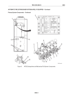
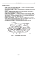
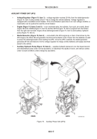
AFES Fire Sensors (Figure 8, Item 13)
— detects if a fire is present and sends a fire signal to the CEP
(Figure 8, Item 2). Five sensors, S1 through S5 (Figure 8, Item 13), are positioned throughout the engine
compartment. Relative to the engine compartment, S1 is located in the operator front, S5 is located
immediately behind S1, S2 is located in the mechanic front, S3 is located in the operator rear, and S4 is
located in the mechanic rear.
•
Extinguishers With FM-200BC Agent (Figure 8, Item 1) and Extinguisher Shots
— five 10-lb (5-kg)
bottle-and-control-valve assemblies (Figure 8, Item 7) are located on the operator side of the crew
compartment. From operator to mechanic (rear to front), they are E5 or MECH shot (MECH), E1 and E2
or ENG 1 shot (ENG 1), and E3 and E4 or ENG 2 shot (ENG 2). Each bottle contains 10 lb (5 kg)
HFC-227 ea (FM-200) and 0.5 lb (0.2 kg) sodium bicarbonate to produce HFC-227bc (FM-200BC) with a
temperature-dependent nitrogen charge (900 psi (6,205 kPa)) at 70°F (21°C).
•
Alarm Control Box (ACB) (Figure 8, Item 6)
— processes AFES engine fire warning and BIT fault
signals generated by AFES fire sensors (Figure 8, Item 13).
•
Discharge Linkage for Dual and Single Extinguisher Shots
— a separate dual linkage connects each
of the ENG 1 (E1 and E2) control valve levers (Figure 8, Item 9) and the ENG 2 (E3 and E4) control valve
levers (Figure 8, Item 8) so the extinguishers are synchronized on these dual extinguisher shots.
•
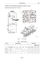
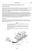
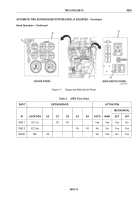
Mechanical Pull Cable Operation
— the MECH extinguisher E5 has a single linkage (Figure 8, Item 11)
and single discharge (Figure
8, Item 10). The locking pin(s) (Figure 8, Item 12) must be removed to hand
operate an extinguisher. See Table 5.
•
Dual Pull Mechanism (Figure 8, Item 4)
— connects the cables of the interior and exterior ENG 2
remote pull cable handles so that pulling either one will discharge the extinguishers.
•
Exterior Remote Pull Cable Handles (Figure 8, Item 3)
— located on the operator side of the vehicle,
forward of the crew door. The two pull handles are left to right (vehicle front to rear) to discharge ENG 1
and ENG 2, respectively.
•
Interior Remote Pull Cable Handles (Figure 8, Item 5)
— located on the crew compartment just above
the CEP (Figure 8, Item 2). The two pull handles are left to right (vehicle rear to front) to discharge the
ENG 2 and the MECH, respectively.
TM 9-2350-256-10
0003
0003-8
Back to Top

