TM-9-2350-256-10 - Page 45 of 796
FUEL SUPPLY SYSTEM
•
Fuel Tank Supply
— three fuel tanks supply fuel to the engine, the APU, and the refuel system. Two
tanks are adjacent to the engine, one on either side, and the third tank is forward of the bulkhead in the
winch compartment. A system of four manually operated control valves maintains fuel flow through the
check valve and directs fuel to the engine and refueling systems. These valves are also used to drain the
fuel tanks.
•
Hand-operated Purge Pump
— next to the operator's seat, provides a means of purging the fuel injector
pump, fuel filters, and engine fuel lines of air. The air is forced by the fuel pressure from the purge pump
through the engine fuel lines and back to the fuel tanks through the injector pump fuel return line.
AIR INTAKE SYSTEM
•
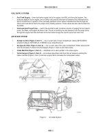
Damper Control (Figure 3, Item 1)
— one on each side of crew compartment. Allows AIR SOURCE
selection between OUTSIDE air or INSIDE (crew compartment) air.
•
Dry-type Air Filter (Figure 3, Item 2)
— one on each side of the crew compartment. Filters dust and dirt
from the air before it enters the turbochargers (Figure 3, Item 4) and main engine.
•
Intake Manifold (Figure 3, Item 3)
— distributes air to each cylinder in the main engine.
•
Turbochargers (Figure 3, Item 4)
— are exhaust gas-driven and boost the air pressure entering the
intake manifold (Figure 3, Item 3) and main engine which increases the horsepower output.
Figure 3.
Air Intake System.
TM 9-2350-256-10
0003
0003-3
Back to Top

