TM-9-2350-261-20-1 - Page 168 of 346
TM 9-2350-261-20-1
CHARGING SYSTEM MALFUNCTIONS
0018 00
INITIAL SETUP:
Maintenance Level
Unit
Tools and Special Tools
Digital Multimeter (WP 0780 00, Item 43)
General Mechanic’s Tool Kit (WP 0780 00, Item 29)
Inspection Mirror (WP 0780 00, Item 42)
Jumper Wire
Personnel Required
Unit Mechanic
References
See your -10
Equipment Condition
Engine stopped/shutdown (see your -10)
Carrier blocked (see your -10)
Trim vane lowered (see your -10)
Power plant front access door open (see your -10)
Driver’s power plant access panel removed (see your
-10)
Power plant rear access panels removed (see your -10)
Engine disconnect lever IN (see your -10)
T
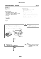
1.
Start engine and run at 1200 RPM (see your -10).
2.
Remove cap (1) from slave receptacle (2).
3.
Measure voltage between contacts (+) (3) and (-) (4) on
auxiliary power receptacle.
4.
Does multimeter read less than 26 or more than 29 volts?
TN
1.
Stop engine (see your -10).
2.
Go to Battery/Generator Indicator
Malfunctions (WP 0049 00).
Y
1.
Check generator belt.
2.
Is generator belt tight or in good condition?
YN
1.
Belt needs adjustment or replacement
100 amp (WP 0227 00) or 200 amp
(WP 0228 00).
001800-1
Back to Top


