TM-9-2350-261-20-2 - Page 883 of 1008
TM 9-2350-261-20-2
REPLACE ENGINE POWER DISCONNECT
0408 00
THIS WORK PACKAGE COVERS:
Removal (page 0408 00-1).
Installation (page 0408 00-2).
Adjustment (page 0408 00-3).
INITIAL SETUP:
Maintenance Level
Unit
Tools and Special Tools
General Mechanic’s Tool Kit (WP 0780 00, Item 29)
Torque wrench (WP 0780 00, Item 102)
Materials/Parts
Antiseize compound (WP 0782 00, Item 8)
Cotter pin
Locknut (2)
Tab washer (2)
Personnel Required
Unit Mechanic
Equipment Condition
Engine stopped/shutdown and ramp lowered (see your
-10)
Carrier blocked (see your -10)
Trim vane lowered (see your -10)
Power plant rear access panel removed (WP 0431 00,
WP 0432 00, or WP 0433 00)
Driver’s power plant access panel removed
(WP 0430 00)
REMOVAL
1.
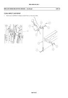
Remove two screws (1), locknuts (2), supports (3), one lock (4), bushing (5) and spring (6) from lever (7). Discard
locknuts.
2.
Remove cotter pin (8) and pin (9) that secures lever (7) to arm (10). Discard cotter pin.
3.
Remove lever (7) from guide (11).
4.
Remove two screws (12), tab washers (13), and guide (11) from transmission housing. Discard tab washers.
040800-1
Back to Top


