TM-9-2350-261-20-2 - Page 877 of 1008
INITIAL SETUP:
Maintenance Level
Unit
Tools and Special Tools
Materials/Parts
Locknut (2)
Spring pin
Personnel Required
Unit Mechanic
References
Equipment Condition
Engine stopped/shutdown (see your -10)
Carrier blocked (see your -10)
A ir cleaner housing and elem ent r emoved (
WP 0185 00
)
A ir c o ntrol valve rem ov ed (
WP 0187 00
)
REMOVAL
1.
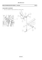
Remove two screws (1), locknuts (2), and range selector link (3) from arm (4) and transmission cross-shaft (5). Discard
locknuts.
2.
Remove spring pin (6) and arm (4) from range selector (7). Discard spring pin.
General Mechanic’s Tool Kit (WP 0780 00, Item 29)
THIS WORK PACKAGE COVERS:
Removal (page 0407 00-1).
Clean, Inspect, and Repair (page 0407 00-2).
Installation (page 0407 00-3).
Adjustment (page 0407 00-4).
REPLACE RANGE SELECTOR LINKAGE
0407 00
TM 9-2350-261-20-2
040700-1
WP 0404 00
Back to Top


