TM-9-2350-261-20-2 - Page 870 of 1008
REPAIR TRANSMISSION RANGE SELECTOR — Continued
ASSEMBLY
1.
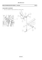
Install shaft (1) and cam (2) in housing (3). Secure cam to shaft with new spring pin (4).
2.
Install control lever assembly (5) and spring (6) in housing (3). Secure control lever to shaft (1) with pin (7) and new
cotter pin (8).
3.
Install lock (9) on control lever (5). Secure with new spring pin (10).
4.
Install control rod (11), spring (12), and washer (13) in control lever (5).
5.
Securerod(11)tolock(5)andlever (5) with three new cotter pins (14).
6.
Install neutral start switch (15) in housing (3). Secure with two screws (16), washers (17), new lockwashers (18),
and nuts (19).
7.
Install two pins (20) in housing (3).
8.
Secure cover (21) to housing (3) with two screws (22).
9.
Inst all r ange selector in carrier (
WP 0404 00
).
1 0.
A djust ran ge selecto r lin kage (
WP 0407 00
).
11.
Adjust neutral start switch (
WP 0406 00
).
0405 00-4
0405 00
TM 9-2350-261-20-2
Back to Top


