TM-9-2350-261-20-3 - Page 254 of 932
TM 9-2350-261-20-3
REPLACE/REPAIR DRIVER’S SEAT POST ASSEMBLY — Continued
0483 00
4.
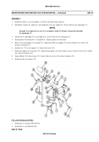
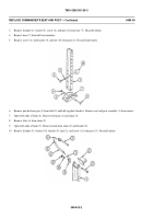
Remove four screws (14), washers (15), locknuts (16), and support (17) from adjuster (18). Discard locknuts.
5.
Remove screw (19), washer (20), and spring cover (21) from adjuster (18). Remove cover.
6.
Remove cotter pin (22), washer (23), pin (24), washer (23), and spool (25) with two springs (26) from adjuster (18).
Remove springs from spool. Discard cotter pin.
7.
Remove four snap rings (27) and rollers (28). Use snap ring pliers.
8.
Work through slot on top of adjuster (18), and remove two spring pins (29) from cam (30). Remove crank (31). Discard
spring pins.
9.
Compress spring (32) against wall of adjuster (18). Remove two spring pins (33) from straight pin (34). Remove straight
pin, two washers (35), and cam (30) from inside adjuster. Discard spring pins.
10. Remove spring (32) and washer (36) from adjuster (18).
0483 00-4
Back to Top

