TM-9-2350-261-20-3 - Page 671 of 932
REPLACE RAMP PUMP — Continued
INSTALLATION
1.
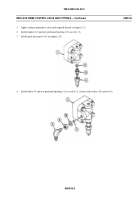
Install new packing (7) and reducer (6) in pump (5).
2.
Install jamnut (1) on elbow (2). Install new packing (4), new ring (3) and elbow (2) in pump (5). Secure elbow with
jamnut.
3.
Install pump (5) and new gasket (8) in bracket (9). Install four screws (10). Secure with new lockwire (11).
NOTE
Retaining ring needs to be installed first. It protects coupling from rubbing against bracket.
During coupling installation, tabs on two tab washers must face away from pump. Otherwise,
pump will not work.
4.
Installnewretainingring(12)andcoupling(13)onpump(5).
5.
Install new packing (14) on bracket (9).
tabs on washers to secure screws.
7.
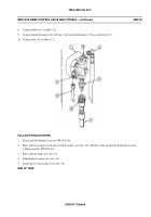
Connect pump outlet tube (17) to elbow (2).
8.
Connect pump inlet hose (18) to pump (5).
058800-3
0588 00
TM 9-2350-261-20-3
6.
Install bracket (9), with pump (5) attached, in transfer gearcase. Secure with two new tab washers (15) and screws (16).
TIGHTEN SCREWS TO 144-180 LB-IN (16-20 N·M) TORQUE. Use torque wrench and socket wrench set. Bend
Back to Top


