TM-9-2350-261-34 - Page 622 of 785
TM 9-2350-261-34
REPAIR ROADSIDE AND CURBSIDE DATA PANEL ASSEMBLIES
A12 AND A13 (M1068 ONLY)
0082 00
THIS WORK PACKAGE COVERS:
Disassembly (page 0082 00-1).
Assembly (page 0082 00-4).
INITIAL SETUP:
Maintenance Level
Direct Support
Tools and Special Tools
Radio Equipment Tool Kit (WP 0104 00, Item 47)
Materials/Parts
Locknut (4)
Lockwasher (14)
Personnel Required
Radio Repairer 29E10
Equipment Condition
Data box removed (see your -20)
DISASSEMBLY
NOTE
Tag all leads before removal for proper installation later.
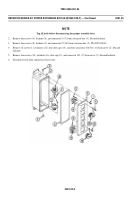
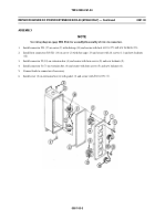
Follow illustration for removal/installation of red/black binding posts.
See wiring diagrams (page 0082 00-6) for disassembly/assembly of wires to connectors/binding
posts.
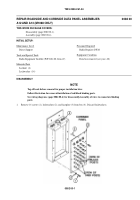
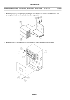
1.
Remove 14 screws (1), lockwashers (2), and faceplate (3) from box (4). Discard lockwashers.
008200-1
Back to Top


