TM-9-2350-261-34 - Page 631 of 785
TM 9-2350-261-34
REPAIR POWER CONTROL ENCLOSURE, RIGHT PANEL (M1068 ONLY) — Continued
0083 00
9.
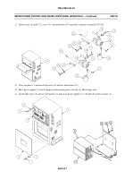
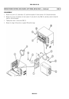
Remove circuit leads 20B, 18D, and 3AC (19) from connector J37 (20).
10. Remove circuit leads 11A, 28A, 12A, 28B, and 3W (21) from J27 (22).
11. Remove circuit lead 44A (23) from J28 (24).
12. Remove circuit 34A (25) from J29 (26).
13. Remove 16 screws (27), locknuts (28), and connectors J37 (20), J27 (22), J28 (24), and J29 (26) from enclosure (18).
Discard locknuts.
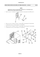
14. Remove circuit leads 22A, 21A, 3AA, 18C, and 27A (1) from ground fault interrupter (2). Remove two screws (3),
lockwashers (4), and ground fault interrupter (2) from enclosure (5). Discard lockwashers.
NOTE
See wiring diagram (page 0083 00-9) to disconnect wires from terminal blocks. There are set
screws securing each wire.
0083 00-4
Back to Top


