TM-9-2350-277-20-2 - Page 513 of 783
TM 9-2350-277-20-2
REPLACE THROTTLE VALVE (TV) MODULATOR AND LEVER — Continued
0218 00
4.
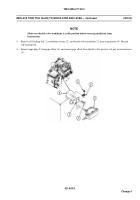
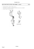
Install lever (7) in throttle shaft (8). Secure with screw (9), two washers (10), and new locknut (11).
5.
Install nut (12) and anchor (13) on cable (14).
6.
Install anchor (13) with cable (14) in lever (7). Secure with washer (15) and new locknut (16).
7.
Install nut (17) on cable (14).
8.
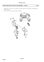
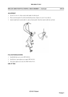
Tighten jamnut (1) on cable (2) 4-7/16 to 4-9/16 inch (11.27 to 11.58 cm) from bracket (3) to end of shield covering
inner cable.
9.
Adjust throttle valve modulator (WP 0213 00).
FOLLOW-THROUGH STEPS
1.
Install exhaust elbow (WP 0221 00).
2.
Install air intake elbow (WP 0173 00).
3.
Install driver’s power plant access panel (WP 0441 00).
4.
Close power plant access door. See TM 9-2350-277-10.
END OF TASK
0218 00-5/6 blank
Change 5
Back to Top

