TM-9-2350-277-34 - Page 167 of 871
TM 9-2350-277-34
REPLACE ENGINE — Continued
0015 00
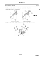
53. Install clamp (6) with hose (1) on transmission. Use existing screw (4), washer (5), and nut (7).
54. Connect hose (1) to elbow (2) on transmission end cover (3).
5 5.
In st a ll new p ref or m ed p ackin g (17 ) a nd t herm ost atic swit ch (1 0) on p ower plan t (
o
l d
c
on fig ur atio n).
5 6.
C on nect pressu re ho se (14) to adapter (1 6) o n t
her m o s tati c s wi tch ( 10)
(
o
ld
c
on fi gur atio n) .
57.
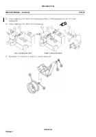
Install sensor (17.6) on thermostat hou sing (
n
ew
c
on figuratio n).
58.
Install bracket assem bly (17.5) and secure w ith two screw
s ( 7.3) and t wo lo ckwash ers (17 .4 ) (
n
e w
c
on fig uratio n).
5 9.
In stall ho se (17.1) on valve (17 .2 ) (
n
e w
c
on fig uratio n).
0015 00-34
Change 2
Back to Top


