TM-9-2350-277-34 - Page 656 of 871
TM 9-2350-277-34
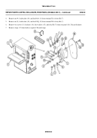
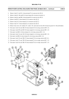
REPLACE INVERTER AND INVERTER HOUSING ASSEMBLY A2
(M1068A3 ONLY) (ALL EXCEPT OUTBACK)
0094 00
THIS WORK PACKAGE COVERS:
Removal (page 0094 00- 1).
Installation (page 0094 00-6).
INITIAL SETUP:
Maintenance Level
Direct Support
Tools and Special Tools
General Mechanic’s Tool Kit (WP 0120 00, Item 62)
Materials/Parts
Lockwasher (12)
Lockwasher (6)
Lockwasher (4)
Self-locking nut (16)
Self-locking nut (8)
Self-locking nut (8)
Self-locking nut (4)
Self-locking nut (3)
Self-locking nut (2)
Personnel Required
Power-Generation Equipment Repairer 52D10
Helper (H)
Equipment Condition
Engine stopped (TM 9-2350-277-10)
Carrier blocked (TM 9-2350-277-10)
All external power disconnected
(TM 11-7010-256-12&P)
Battery ground lead disconnected
(TM 9-2350-277-20-3)
Power control enclosure removed
(TM 9-2350-277-20-6)
REMOVAL
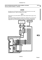
NOTE
Replacement of old quasi-sine wave inverters (25-pin) with new true-sine wave inverters
(15-pin) requires the cascade remote harness be replaced at the same time. If one inverter in a
set fails you need to replace it with a similiar model. If you cannot replace it with a similiar
model you will need to replace both inverters as a set. It is not necessary to remove the housing
to remove one or both inverters.
009400-1
Change 5
Back to Top


