TM-9-2350-277-34 - Page 664 of 871
TM 9-2350-277-34
CAUTION
If retaining screws at W15 connector loosen or fall out, the W15 connector can cause a short
and damage the inverter. Make sure retaining screws are tight.
NOTE
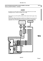
Wiring leads for inverters IN1 and IN2 are different, follow schematic below for proper wiring
connections.
The W15 cable is different for old and new model inverters. Old quasi-sine wave inverters have
a 25-pin connector configuration and new true-sine wave inverters have a 15-pin connector
configuration. They are not interchangeable. See Table 1 for correct harness configuration.
009400-9
Change 5
REPLACE INVERTER AND INVERTER HOUSING ASSEMBLY A2 (M1068A3
ONLY) (ALL EXCEPT OUTBACK) — Continued
0094 00
Back to Top


