TM-9-2350-277-34 - Page 667 of 871
TM 9-2350-277-34
REPLACE INVERTER AND INVERTER HOUSING ASSEMBLY A2 (M1068A3
ONLY) (ALL EXCEPT OUTBACK) — Continued
0094 00
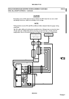
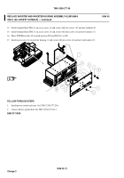
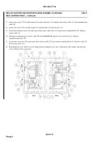
14. Install terminal block TB1 (9) on access cover (4) and secure with two screws (10) and new locknuts (8).
15. Install terminal block TB2 (3) on access cover (4) and secure with four screws (2) and new locknuts (7).
16. Move POWER switch (45) on both inverters IN1 and IN2 (23) to ON.
17. Install access cover (4) on inverter housing (1) and secure with ten screws (6) and new lockwashers (5).
FOLLOW-THROUGH STEPS
1.
Install power control enclosure. See TM 9-2350-277-20-6.
2.
Connect battery ground lead. See TM 9-2350-277-20-3.
END OF TASK
0094 00-12
Change 5
Back to Top


