TM-9-2350-277-34 - Page 661 of 871
TM 9-2350-277-34
INSTALLATION
NOTE
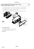
Both inverters are installed the same way except for wiring leads. Inverter IN2 is installed as
shown. Inverter IN1 installs on the left side and is not shown for clarity. When replacing one
inverter the replacement must be the same type/model. Older model inverters have a 25-pin
connector, the new true-sine wave inverters have a 15-pin connector.
1.
Install mounting strip (41), inverter housing (1), bezel (42), and three screws (43) on sponson.
2.
Install four resilient mounts (44) on inverter housing (1) and secure with eight screws (40), washers (39), and new
locknuts (38).
0094 00-6
Change 5
REPLACE INVERTER AND INVERTER HOUSING ASSEMBLY A2 (M1068A3
ONLY) (ALL EXCEPT OUTBACK) — Continued
0094 00
Back to Top


