TM-9-2350-311-10 - Page 292 of 775
TM 9-2350-311-10
2-12 PREPARATION FOR FIRING — CONTINUED
2-12.3
Standard Angle Method — Continued
a.
Determining the Standard Angle — Continued
NOTE
•
The scribe line at the junction of the muzzle brake and cannon tube verifies that the muzzle
brake has not shifted. Therefore, the standard angle should remain unchanged.
•
Scribe lines must be alined when installing the muzzle brake after maintenance. If the scribe
lines don’t match, fire control alinement tests must be performed, new scribe lines made,
and new standard angle determined.
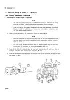
4
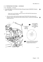
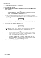
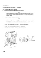
Scribe a line at the junction of the muzzle brake (4) and the cannon tube (5).
NOTE
•
Alining the scribe lines on cross-level mechanism knob and the cross-level mechanism and
the scribe lines on pitch level knob and bracket serves as the coarse alinement indices for
these two mounts.
•
The marks placed on the Ml 45/M145A1 telescope mount cross-level knob and pitch level
knob serve as the fine indices for conducting the standard angle test.
5
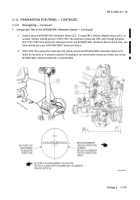
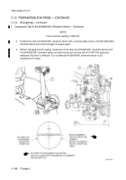
Rotate the M145/M145A1 telescope mount (6) cross-level mechanism knob (7) until scribe lines on
cross-level mechanism knob and cross-level mechanism (8) aline.
6
Rotate the M145IM145A1 telescope mount (6) pitch level knob (9) until scribe lines on pitch level knob
and bracket (10) aline.
2-194
Back to Top


