TM-9-2350-311-20-1 - Page 1023 of 1275
TM9-2350-311 -20-1
SECTION Ill. TRAVEL LOCK, SPADE, FENDERS, AND TOWING PINTLE
11-14 TRAVEL LOCK
This task covers:
a. Removal
b. Disassembly
c. Assembly
d. Installation and Adjustment
e. Adjustment
INITIAL SETUP
T
OO
I
S
General mechanic’s tool kit (item 64 App
X
H
Sling (item 60, Appx H)
Socket wrench set (item 56, App
X
H)
Torque wrench (item 71, App
X
H)
Adhesive (item 2, Appx D)
Cap lining (item 161, Appx G)
Cotter pins (2) (item 52, Appx G)
Cotter pins (3) (item 49, Appx G)
Lockwashers (6) (item 89, Appx G)
Primer (item 74, Appx D)
Self-locking nuts (7) (item 223, Appx G)
Wire rope sleeves (2) (item 152, Appx G)
Wire ropes (2) (item 159, Appx G)
a. Removal
WARNING
Gun tube must be out of support. Support arm is heavy and must be secured with
hoist or laid down to prevent support arm falling and causing serious injury or death.
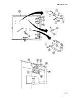
1 Remove pin assembly (1).
2 Lift handle (2) to unfasten travel lock cap (3).
3 Elevate and traverse cannon tube (4) to clear travel lock.
WARNING
Travel lock must be secured to avoid possible injury during removal.
4 Secure travel lock cap (3). Replace pin assembly (1).
NOTE
Steps 5 thru 13 remove travel lock without removing mounting bracket. Step 14 thru
17 removes travel lock with mounting bracket attached.
11-44
Back to Top


