TM-9-2350-311-20-1 - Page 1031 of 1275
TM9-2350-311 -20-1
11-14 TRAVEL LOCK — CONTINUED
d. Installation and Adjustment
1
Traverse cannon tube (4) to forward center of vehicle.
2
Put cab in manual traverse mode and engage traverse lock. Insure that lock is fully engaged by attempting to
traverse.
3
Elevate cannon tube (4) to clear travel lock (8).
Support arm is heavy. Be careful when raising or lowering travel lock and during
installation of counterbalance springs to avoid serious injury.
4
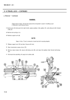
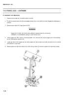
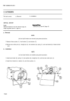
Place support arm (8) in center of mounting bracket (12). Insert pin (20). Ensure support arm is still centered.
Do not install spacer washers (18).
5
Lower gun tube (4) into support arm (8). Slide support arm (left to right) on pin (20) until center of arm is alined
with centerline of gun tube.
6
Rotate support arm (8) front to back on pin (20) until gun tube (4) lies flat on support arm cap lining surface.
11-52
WARNING
Back to Top

