TM-9-2350-311-20-1 - Page 1033 of 1275
TM9-2350-311-20-1
11-14 TRAVEL LOCK — CONTINUED
d. Installation and Adjustment — Continued
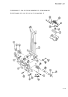
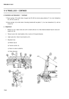
11 Secure springs (14) to both sides of support arm (8) with two torsion spring retainers (7), four new Iockwashers
(6), and four screws (5).
12 Secure springs (14) to both sides of mounting bracket with two plates (11), four new Iockwashers (10), and four
screws (9).
e. Adjustment
1
2
3
4
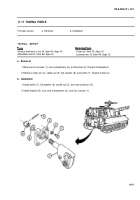
Remove nut (41). Adjust screw (42) until it contacts with pin (13). Note distance between head of screw and
support arm (8).
Remove screw (42); install washers (43) on screw to fill required distance.
Install screw (42). Check fit and install nut (41).
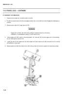
Adjustment test:
(a) Release cap (3).
(b) Traverse cannon (4).
(c) Return to cannon centerline.
(d) Check alinement.
11-54
Back to Top


