TM-9-2350-311-20-1 - Page 1029 of 1275
TM9-2350-311 -20-1
11-14 TRAVEL LOCK — CONTINUED
c. Assembly — Continued
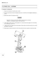
WARNING
Mounting bracket is heavy. Two personnel are required to support
bracket during
installation to avoid serious injury.
4
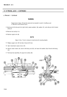
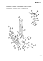
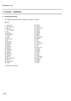
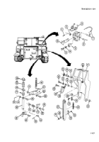
Install mounting bracket (12) and seven screws (24). Install seven flat washers (26) and seven new self-locking
nuts (25) from inside engine compartment. Torque nuts 350-370 Ib-ft (475-502 N•m).
5
Install new wire rope assembly (40) on Iockpin (13). Install wire rope assembly with Iockpin on bracket (12).
6
Install nut (39) and tee (38) on clevis (37).
7
Install handle (2), headed pin (31), flat washer (30), and new cotter pin (29) on support arm (8).
8
Install clevis (37), pin (35), flat washer (34), and new cotter pin (33) on handle (2).
9
Install new wire rope assembly (36) and Iockpin (1) on support arm (8).
10 Apply adhesive to new cap lining (32) surface and install new cap lining.
11 Install travel lock cap (3), headed pin (31), flat washer (30), and new cotter pin (29) on support arm (8).
11-50
Back to Top


