TM-9-2350-311-20-1 - Page 155 of 1275
TM9-2350-311-20-1
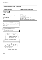
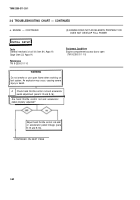
(3) ENGINE CRANKS FOR SHORT TIME ONLY;
BATTERY POWER LEVEL IS CORRECT
INITIAL SETU P
Applicable Configurations
.
.
M109A4/M109A5
Personnel Required
.
Two
Tools
Equipment Conditions
. .
General mechanic’s tool kit (item 64, Appx H)
Transmission left access door open (TM 9-2350-311-1 0)
Multimeter (item 36, Appx H)
Battery access doors open (TM 9-2350-31 1-10)
TA-1 probe kit (item 43, AppX H)
Portable instrument panel cover removed (para 8-17)
(Long test leads may be needed for some tests;
16 AWG wire maybe used as an extension.)
2.
3.
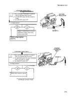
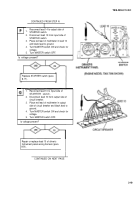
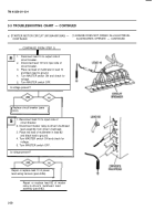
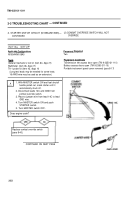
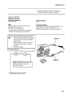
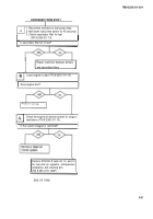
Disconnect driver’s bulkhead-to-master
relay wiring harness from starter protection
relay and inline connector-to-powerplant
wiring harness.
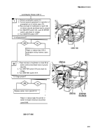
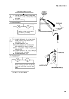
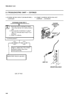
Place red lead of multimeter in socket C
(lead 503) and black lead on lead 503
connector.
Check for continuity.
I
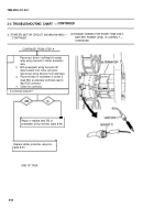
Is continuity present?
Repair or replace lead 503 of driver's
bulkhead-to-master relay wiring
harness (para 8-46).
I
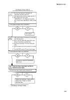
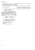
CONTINUED ON NEXT PAGE
3-55
Back to Top

