TM-9-2350-311-20-1 - Page 348 of 1275
TM 9-2350-311 -20-1
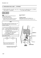
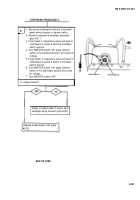
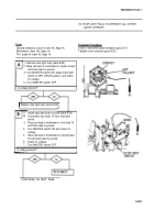
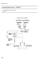
3-3 TROUBLESHOOTING CHART — CONTINUED
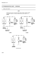
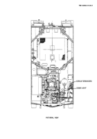
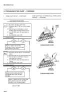
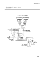
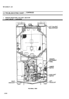
u. SERVICE HEADLIGHTS, TAILLIGHT, AND STOP (2) HEADLIGHTS OPERATE ON ONE BEAM ONLY
LIGHT CIRCUIT — CONTINUED
Tools
Personel
Required
General mechanic’s tool kit (item 64, Appx H)
Two
Multimeters (item 36, Appx H)
TA-1 probe kit (item 43, App
X
H)
Equipment Condition
(Long test leads may be needed for some tests;
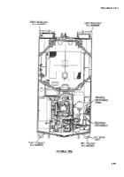
Engine access door open (TM 9-2350-311-1 O)
16 AWG wire may be used as an extension.)
Transmission access doors open (TM 9-2350-311-1 O)
NOTE
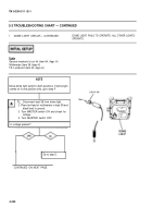
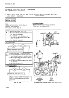
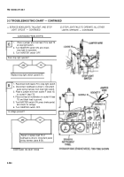
Both headlight assemblies have identical wiring. The
following procedures apply to both right and left
headlight assemblies.
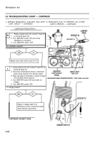
1
A
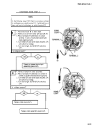
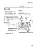
1. Remove inoperative headlight assembly
(para 8-21 ).
2. If low beam is inoperative, place red lead of
multimeters in socket A (lead 18) and black
lead to ground.
3. Turn MASTER switch ON, place dimmer
switch in the low beam position, and check for
voltage.
4. If high beam is inoperative, place red lead of
multimeters in socket B (lead 17) and black
lead to ground.
5. Turn MASTER switch ON, place dimmer
switch in the high beam position, and check
for voltage.
6. Turn MASTER switch OFF.
Is voltage present?
Replace sealed beam unit (para
8-22).
1
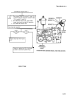
CONTINUED ON NEXT PAGE
3-248
Back to Top

