TM-9-2350-311-20-1 - Page 466 of 1275
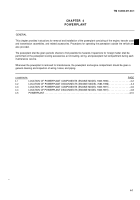
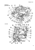
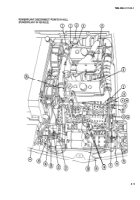
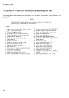
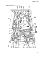
4-2 LOCATION OF POWERPLANT DISCONNECTS (ENGINE MODEL 7083-7396)
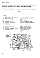
The following legend and illustrations are for reference only. For removal and installation of the powerplant, see
paragraph 4-5.
NOTE
M109A4/M109A5 powerplant ground cable is located at starter. For information on
disconnect points of winterizafion kit, see Chapter
LEGEND
1
2
3
4
5
6
7
8
9
10
11
12
13
14
15
16
17
18
Engine-to-lower fuel tank return hose and clamp
Engine exhaust pipe flanges
Fixed fire extinguisher nozzle
Air cleaner duct hose at turbocharger inlet
Governor fuel shutoff Iever, pulley, and cable
Throttle governor control rod
Throttle governor control rod (linkage)
Steer control rod
Throttle control tube
Accelerator and throttle control bracket
Tachometer flexible driveshaft
Speedometer flexible driveshaft
Shift control rod
Master relay and voltage regulator disconnects
Final drive universal joints
Transmission trunnion caps
Brake control sprocket, shaft, and pin
Engine starter cable and master circuit harness
19
20
21
22
23
24
25
26
27
28
29
30
31
32
33
34
14.
Powerplant ground cable (M109A2/M109A3)
Alternator-to-rectifier harness (at rectifier)
Coolant pump-to-surge tank hose clamps
Primary fuel filter input hose
Speedometer right angle rod
Coolant surge tank, retainer, and pad
Separation of starter cable and generator-to-
rectifier harness
Air cleaner duct hose
Engine compartment access cover
Engine mount release shaft
Throttle valve control rod linkage
Brake control sprocket and shaft
Master relay and voltage regulator
Transmission support caps
Powerplant ground cable terminal (M109A2/
M109A3)
Bilge pump hose and tube (para 11-18)
4-4
TM9-2350-311-20-1
Back to Top

