TM-9-2350-311-20-1 - Page 697 of 1275
8-20 ACCESSORY CONTROL BOX — CONTINUED
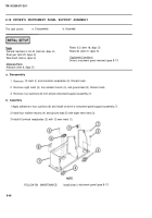
b. Disassembly/Repair
NOTE
Some accessory control boxes may have additional wiring for the flotation blower.
This wiring is no longer used.
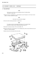
1 Remove 12 nuts (10), 12 Iockwashers (11), 12 flat washers (12), and 12 screws (13). Lift off cover (14) and
gasket (15). Discard lockwashers and gasket.
NOTE
Follow step 2 only if ground lead is damaged.
2 Drill out rivet (16) to remove ground lead (17). Discard rivet.
NOTE
For accessory control box wiring diagram (lD/schematic), refer to personnel heater
and personnel ventilation blower troubleshooting procedures (para 3-3).
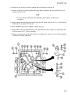
3 Disconnect four electrical connectors (18) at circuit breakers (19).
4 Remove four screws (20), four flat washers (21), four lockwashers (22), and four nuts (23). Remove two circuit
breakers (19). Discard lockwashers.
5 Remove screw (24), two flat washers (25), and nut (26).
8-52
TM 9-2350-311-20-1
Back to Top

