TM-9-2350-311-20-1 - Page 702 of 1275
TM 9-2350-311-20-1
8-21 HEADLIGHTS
This task covers:
a. Alinement
b. Removal
c. Installation
d. Adjustment
T
OO
I
S
.
Materials/Parts
General mechanic’s tool kit (item 64, Appx H)
Silicone compound (item 18, Appx D)
a. Alinement
NOTE
Alinement of lights should be performed in shaded or dimly-lit area.
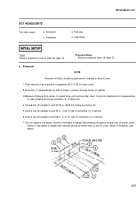
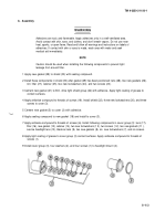
1 Park vehicle on level ground or pavement 25 ft (7.62 m) from a wall.
2
Draw line (1) perpendicular to wall or screen, passing through center of vehicle.
3
Measure distance from center of sealed lamp unit (service side, clear) to ground. Duplicate this measurement
on wall, drawing horizontal centerline (2) of lamp unit.
4 Draw
a
line (3) parallel to and 27.25 in. (69.2 cm) below centerline (2).
5 Draw a line (4) parallel to and 53 in. (1.35 m) left of centerline (1) of vehicle.
6 Draw a line (5) parallel to and 58 in. (1.47 m) right of centerline (1) of vehicle.
7 Turn on lights to low beam. Center of left beam’s highest light intensity should be where lines (3 and 4) cross.
Center of right beam’s highest light intensity should be where lines (3 and 5) cross. Adjust if necessary (see
below).
8-57
Back to Top

