TM-9-2350-311-20-1 - Page 708 of 1275
TM 9-2350-311-20-1
b. Assembly
WARNING
Adhesives are toxic and flammable. Apply adhesives only in a well-ventilated area.
Avoid contact with skin, eyes, and clothes, and don’t breath vapors. Do not use near
heat, sparks, or open flame. Read and follow all warnings and instructions on labels of
adhesives. If contact with skin or eyes is made, wash area with water and seek
medical aid immediately.
NOTE
Caution should be used when installing the following components to prevent light
leakage from around filter.
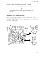
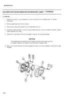
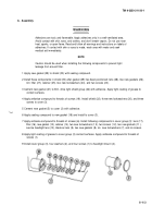
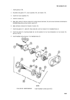
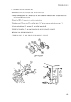
1 Apply new gasket (29) to shield (30) with sealing compound.
2 Install these components in shield (30) after gasket (29) has been positioned: lens (28), two new gaskets (26),
6.0. filter (27), retainer (25), two new Iockwashers (24), and two screws (23).
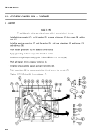
3 Cement new gasket (21) to B.O. drive light shield group (22) with adhesive. Apply light coating of grease to
contact surfaces.
4 Apply antiseize compound to threads of screws (19). Install shield (22), three new Iockwashers (20), and three
screws to cover (3).
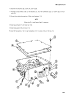
5 Cement new gasket (5) to cover (3) with adhesive.
6 Apply sealing compound to new gasket (18) and install to cover (3).
7 Apply antiseize compound to threads of screws (6). Install following components in cover group (3): lens (17),
filter (16), new gasket (15), retainer (14), two new Iockwashers (1 3), two screws (1 2), two new gaskets (11 ),
service headlight lens (10), blackout lens (9), two new gaskets (8), six
new Iockwashers (7), and six screws.
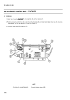
8 Apply light coating of grease to cover group (3) contact surfaces. Apply antiseize compound to threads of
screws (1).
9 Install cover group (3), four washers (2), and four screws (1) to headlight mount (4).
8-63
Back to Top

