TM-9-2350-311-20-1 - Page 716 of 1275
TM 9-2350-311-20-1
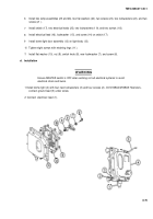
b. Installation
Ensure MASTER switch is OFF when working on telephone terminal to avoid
electrical shock and bums.
NOTE
Position of telephone terminals is different on M109A2/M109A3 and M109A4/M109A5
Howitzers.
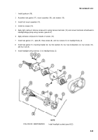
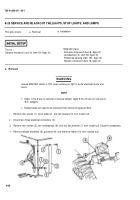
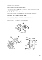
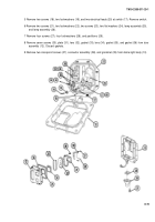
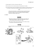
1 Install two new nonmetallic washers (8), two flat washers (7), two flat washers (6), and telephone terminal (5).
2 Install two flat washers (4), two flat washers (3), and two cables (2).
3 Install two nuts (1).
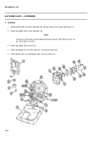
8-27 DOME LIGHT
This task covers:
a. Removal
b. Disassembly/Repair
c. Assembly
d. Installation
T
OO
I
S
Lockwasher (item 71, Appx G)
General mechanic’s tool kit (item 64, Appx H)
Lockwashers (4) (item 95, Appx G)
Materials/Parts
References
Gasket (item 206, Appx G)
TB 9-2300-421-20
Gasket (item 207, Appx G)
TM 9-2350-311-24P&1
Gasket (item 208, Appx G)
a. Removal
Ensure MASTER switch is OFF when working on hull electrical systems to avoid
electrical shock and bums.
8-71
WARNIN G
WARNING
Back to Top

