TM-9-2350-311-20-1 - Page 725 of 1275
TM 9-2350-311-20-1
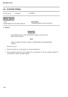
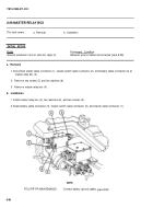
8-29 MASTER RELAY BOX
This task covers:
a. Removal
b. Installation
INITIAL SETUP
Equipment Condition
General mechanic’s tool kit (item 64, Appx H)
Batteries ground cables disconnected (para 8-28)
a. Removal
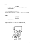
1 Disconnect starter cable connector (1), master switch cable connector (2), and battery cable connector (3) at
master relay box (4).
2 Remove
3 Remove
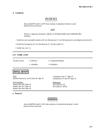
b. Installation
two screws (5) and two washers (6).
master relay box (4).
1 Install master relay box (4), two washers (6), and two screws (5).
2 Install battery cable connector (3), master switch cable connector (2), and starter cable connector (1).
FOLLOW-ON
NOTE
MAINTENANCE:
Connect battery ground cables
(para 8-28)
8-80
Back to Top

