TM-9-2350-311-20-1 - Page 733 of 1275
TM 9-2350-311-20-1
8-34 CIRCUIT BREAKERS (M109A4/M109A5)
This task covers:
a. Removal
b. Installation
Applicable Conditions
.
.
M1 09A4/M109A5
Tools
General mechanic’s tool kit (item 64, Appx H)
Materials/Parts
Lockwashers(16) (item 85, Appx G)
Lockwashers (2) (item 95, Appx G)
. .
Equipment Conditions
Portable and driver's instrument panels removed
(para 8-17)
a. Removal
1
2
3
4
5
6
7
Ensure
MASTER
switch is
OFF
when working on hull electrical systems to avoid
electrical shock and bums.
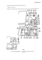
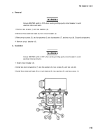
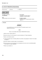
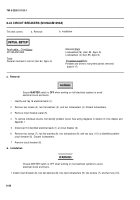
Identify and tag 16 electrical leads (1).
Remove two screws (2), two flat washers (3), and two Iockwashers (4). Discard Iockwashers.
Remove circuit breaker panel (5).
To remove individual circuits, first identify problem circuit. See wiring diagrams in Section Ill, this chapter and
Appendix 1.
Disconnect 16 identified electrical leads (1) at circuit breaker (6).
Remove two screws (7), two flat washers (8), two Iockwashers (9), and two nuts (1 O) at identified problem
circuit breaker (6). Discard Iockwashers.
Remove circuit breaker (6).
b. Installation
Ensure MASTER switch is OFF when working on hull electrical systems to avoid
electrical shock and bums.
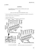
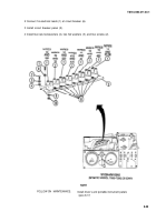
1 Install circuit breaker (6), two flat washers (8), two new Iockwashers (9), two screws (7), and two nuts (10).
WARNING
8-88
Back to Top

