TM-9-2350-311-20-1 - Page 740 of 1275
TM 9-2350-311-20-1
8-38 SLAVE START RECEPTACLE
This task covers:
a. Removal
b. installation
INITIAL SETUP
T
OO
I
S
Lockwashers (2) (item 86, Appx G)
General mechanic’s tool kit (item 64, Appx H)
Lockwashers (4) (item 89, Appx G)
Lockwashers (2) (item 101, Appx G)
Electrical tape — black (item 87, Appx D)
. .
Equipment Conditions
Gasket (item 162, Appx G)
Batteries disconnected (8-28)
NOTE
The M109A2/M109A3 NATO slave start receptacle is located in the bulkhead of the
battery compartment. The M1 09A4/M109A5 NATO slave start receptacle is located in
the driver’s compartment.
a. Removal
1
2
3
4
5
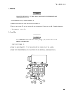
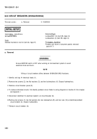
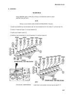
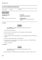
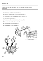
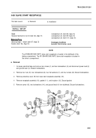
Cut away electrical tape and remove two screws (1) and two Iockwashers (2) and disconnect power lead (3)
and ground lead (4). Discard Iockwashers.
Remove four nuts (5), four Iockwashers (6), four flat washers (7), and four screws (8). Discard Iockwashers.
Remove protective cover (9) from slave start receptacle assembly (10).
Remove receptacle assembly (10), gasket (11 ), and insulator (12). Discard gasket.
Remove screw (13), two lockwashers (14), and ground lead (4) from bulkhead. Discard Iockwashers.
8-95
Back to Top

