TM-9-2350-311-20-1 - Page 739 of 1275
8-37 HEADLIGHT DIMMER AND STOP LIGHT SWITCHES — CONTINUED
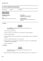
a. Removal — Continued
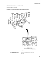
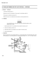
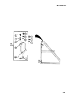
1 Disconnect electrical plug (1).
2 Remove two nuts (2), two washers (3), two screws (4), and dimmer switch (5).
3 Disconnect two electrical connectors (6).
4 Remove two nuts (7), two washers (8), two screws (9), and stop light switch (10).
b. Installation
c.
1
2
3
4
WARNING
Ensure MASTER switch is OFF when working with
electrical shock or bums.
hull electrical systems to avoid
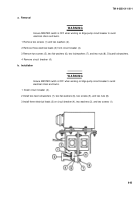
Install stop light switch (10), two washers (8), two screws (9), and two nuts (7).
Connect two electrical connectors (6).
Install dimmer switch (5), two washers (3), two screws (4), and two nuts (2).
Connect electrical plug (1).
Adjustment
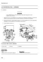
Adjust stop light switch (10) by loosening setscrew (11 ) and stop light actuator (12). Slide actuator right or left so
that stop light goes on when brake pedal (13) is depressed approximately 0.75 in. (19.1 mm). Tighten setscrew.
8-94
TM 9-2350-311-20-1
Back to Top

