TM-9-2350-311-20-1 - Page 736 of 1275
TM 9-2350-311-20-1
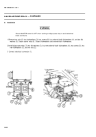
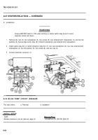
b. Installation
WARNING
systems to avoid
Ensure MASTER switch is OFF when working on hull
electrical shock and burns.
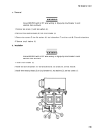
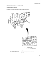
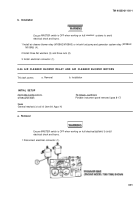
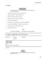
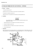
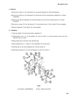
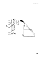
1 Install air cleaner blower relay (M109A2/M109A3) or in-tank fuel pump and generator system relay
M109A5) (4).
2 Install three flat washers (3) and three nuts (2).
3 Install electrical connector (1).
(M109A4/
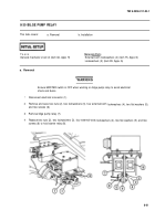
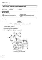
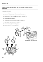
8-36 AIR CLEANER BLOWER RELAY AND AIR CLEANER BLOWER MOTORS
This task covers:
a. Removal
b. Installation
INITIAL SETUP
Applicable Configurations
M109A4/M109A5
Tools
General mechanic’s tool kit (item 64, Appx H)
Equipment
Conditions
Portable instrument panel removed (para 8-17)
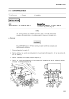
a. Removal
WARNING
Ensure MASTER switch is OFF when working on hull electrical
electrical shock and burns.
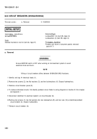
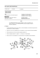
1 Disconnect electrical connector (1).
8-91
electrical
systems to avoid
Back to Top

