TM-9-2350-311-20-1 - Page 728 of 1275
TM 9-2350-311-20-1
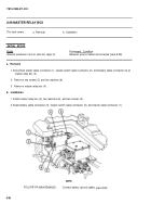
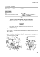
8-31 STARTER RELAY BOX
This task covers:
a. Removal
b. Installation
Tools
General mechanic’s tool kit (item 64, Appx H)
External-tooth Iockwashers (4) (item 75, Appx G)
Lockwashers (2) (item 95, Appx G)
NOTE
The following removal and installation procedures apply to either the starter switch
relay box (M109A2/M109A3) or the starter protection relay box (M109A4/M109A5).
a. Removal
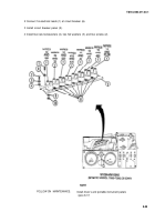
1
2
3
4
Ensure MASTER switch is OFF when working on starter switch relay boxes to avoid
electrical shocks and bums.
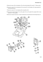
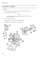
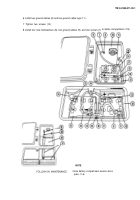
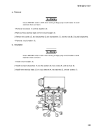
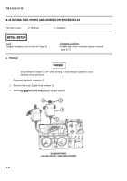
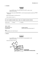
Disconnect electrical connector (1).
Remove and save two nuts (2), two Iockwashers (3), four external-tooth Iockwashers (4), two flat washers (5),
and two screws (6).
Remove starter relay box or starter protection relay box (7).
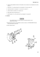
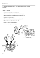
Replace two nuts (2), two Iockwashers (3), four external-tooth
lockwashers (4), two flat washers (5), and two
screws (6) to hold bilge pump relay (8).
8-83
WARNING
Back to Top

