TM-9-2350-311-20-1 - Page 731 of 1275
TM 9-2350-311 -20-1
8-33 CIRCUIT BREAKERS (M109A2/M109A3)
This task covers:
a. Removal
b. Installation
Applicable Conditions
.
.
M109A2/M109A3
Tools
General mechanic’s tool kit (item 64, Appx H)
Material/Parts
Lockwashers (14) (item 85, Appx G)
Lockwashers (2) (item 95, Appx G)
Equipment Condition
Portable and driver's instrument panels removed
(para 8-17)
a. Removal
Ensure MASTER switch is OFF when working on hull electrical systems to avoid
electrical shock and burns.
NOTE
Wiring of circuit breakers differs between M109A2/M109A3 Howitzers.
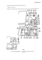
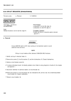
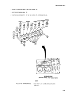
1 Identify and tag 14 electrical leads (1).
2 Remove two screws (2), two flat washers (3), and two Iockwashers (4). Discard Iockwashers.
3 Remove circuit breaker panel (5).
4 To remove individual circuits, first identify problem circuit. Refer to wiring diagrams in Section Ill, this chapter
and Appendix 1.
5 Disconnect identified 14 electrical leads(1) at circuit breaker (6).
6 Remove two screws (7), two flat washers (8), two Iockwashers (9), and two nuts (10) at identified problem
circuit breaker (6). Discard Iockwashers.
7 Remove circuit breaker (6).
6-86
WARNING
Back to Top

