TM-9-2350-311-20-1 - Page 699 of 1275
TM 9-2350-311-20-1
8-20 ACCESSORY CONTROL BOX — CONTINUED
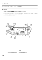
c. Assembly
1
2
3
4
5
6
7
8
9
CAUTIO N
To avoid damaging wiring, use only rosin core solder to connect wires to terminal.
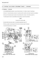
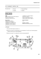
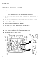
Install electrical connector (42), four flat washers (39), four new lockwashers (40), four screws (38), and four
nuts (41 ).
Install two electrical connectors (37), eight flat washers (34), eight new lockwashers (35), eight screws (33),
and eight nuts (36).
Push indicator light bracket (30) into accessory control box (6).
Apply light coating of silicone compound to three bulb sockets.
Install indicator light lamp assembly (gasket, indicator LED, hex nut, and cap) (31).
Push light bracket (30) into accessory control box (6).
Install two lamp assemblies (gaskets and panel light LEDs) (29).
Push two switches (28) into accessory control box (6) and screw in two hex nuts (27).
Replace WARNING decal (32) if removed (para 2-7).
8-54
Back to Top

