TM-9-2350-311-20-1 - Page 751 of 1275
TM 9-2350-311 -20-1
8-43 POWERPLANT WIRING HARNESS (M109A2/M109A3) — CONTINUED
a. Removal
WARNIN G
Ensure MASTER switch is OFF when working on hull electrical system to avoid
electrical shocks and bums.
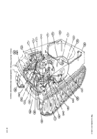
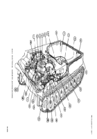
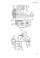
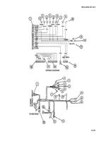
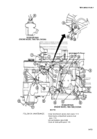
1 Disconnect five connectors (18 thru 22).
NOTE
•
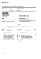
On vehicles with engine model 7083-7396, connectors 14, 15, and 16 are part of
connector 22 and are used for the flame heater system. On vehicles with engine
model 7083-7391, connectors 14, 15, and 16 are part of connector 22 and are
used for the glow plug controller system.
Ž
Access to wires 10 thru 12 will be through driver’s compartment.
Ž
Powerplant must be removed to remove starter leads (9 and 13) (para 4-5).
2 Disconnect 11 connectors (1 thru 8 and 10 thru 12).
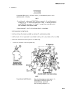
3 Remove two nuts (23) and two flat washers (24). Remove two leads (9 and 13) at starter solenoid (25).
4 Remove two screws (26), two clamps (27), two screws (28), and two clamps (29). Place four screws back into
engine.
5 Remove powerplant wiring harness.
b. Disassembly/Repair
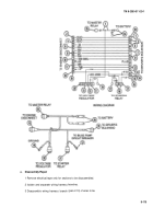
1 Remove electrical tape where necessary for disassembly.
2 Isolate and separate wiring harness branches.
3 Disassemble wiring branch (para 2-13) of wires to be replaced.
c. Assembly
1 Assemble wiring branch (para 2-13) of wires replaced.
2 Apply electrical tape as necessary for assembly.
8-105
Back to Top

