TM-9-2350-311-20-1 - Page 753 of 1275
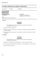
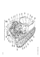
8-44 POWERPLANT WIRING HARNESS (M109A4/M109A5)
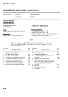
This task covers:
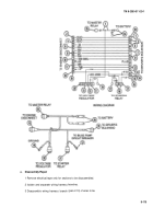
a. Removal
b. Disassembly/Repair
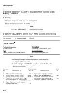
c. Assembly
d. Installation
Lockwashers (4) (item 89, Appx G)
M109A4/M109A5
Lockwashers (4) (item 94, Appx G)
T
OO
I
S
General mechanic’s tool kit (item 64, Appx H)
Air intake grille opened (para 11-8)
Batteries disconnected (para 8-28)
Engine compartment access cover removed (para 11-5)
Electrical tape — black (item 62, Appx D)
Transmission access doors opened (11-7)
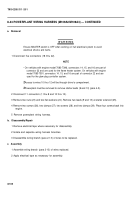
NOTE
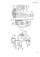
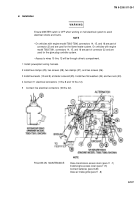
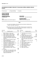
On vehicles with engine model 7083-7396, connector 14 is used for the flame heater
system. On vehicles with engine model 7083-7391, connector 14 is used for the glow
plug controller system.
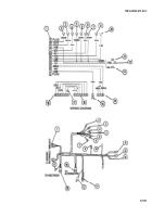
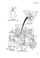
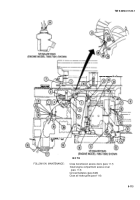
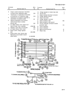
Connector
Wire
Connector
wire
No.
Electrical Lead To:
No.
No.
Electrical Lead To:
No.
1
2
3
4
5
6
7
8
9
Engine disconnect bracket
Low level coolant indicator
Low level coolant indicator
Transmission oil temperature transmitter
Transmission oil temperature switch
Transmission oil pressure switch
Engine coolant temperature switch
Transmission oil pressure transmitter
Engine coolant temperature transmitter
352B
352A
324
5090
509C
509A
321
33A
10
11
12
13
14
15
16
17
18
Starter solenoid coil
14B
Engine oil pressure switch
509B
In-tank fuel pump and generator system
relay switch
76B
Engine oil pressure transmitter
36
Flame heater system connector (engine
model 7083-7396) or glow plug controller
connector (engine model 7083-7391 )
Not used
Alternator
Starter protection relay
To rectifier
588
503
8-108
TM 9-2350-311-20-1
Back to Top

