TM-9-2350-311-20-1 - Page 761 of 1275
TM 9-2350-311-20-1
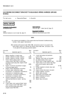
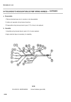
8-45 ENGINE DISCONNECT BRACKET-TO-BULKHEAD WIRING HARNESS (M109A2/
M109A3) — CONTINUED
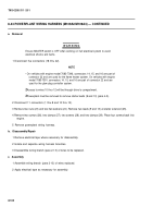
b. Assembly
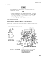
1 Assemble wiring harness branch (para 2-13) of wires replaced.
2 Apply electrical tape as necessary for assembly.
NOTE
FOLLOW-ON MAINTENANCE:
Connect batteries (para 8-28)
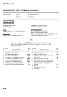
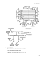
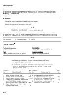
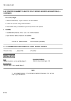
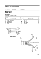
8-46 DRIVER’S BULKHEAD-TO-MASTER RELAY WIRING HARNESS (M109A4/M109A5)
This task covers:
a. Disassembly/Repair
b. Assembly
INITIAL SETUP
Applicable Configurations
M109A4/M109A5
Electrical tape — black (item 62, Appx D)
T
OO
I
S
General mechanic’s tool kit (item 64, Appx H)
Batteries disconnected (para 8-28)
NOTE
•
For removal and installation of the driver’s bulkhead-to-master relay wiring
harness, notify support maintenance.
•
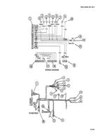
On vehicles with engine model 7083-7396, connector 4 is used for the flame heater
system. On vehicles with engine model 7083-7391, connector 4 is used for the
glow plug controller system.
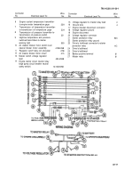
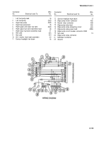
Connector
Wire Connector
Wire
No.
Electrical Lead To:
No. No.
Electrical Lead To:
No.
1
Battery assembly-to-master relay
81 6
Engine coolant temperature transmitter-
2
Aeration detector-to-coolant indicator
352B
to-engine water temperature gage
33A
3
Aeration detector-to-coolant indicator
352A 7
Transmission oil temperature transmitter-
4
Flame heater-to-flame heater switch (engine
to-transmission oil temperature gage
324
model 7083-7396) or glow plug controller-to-
8
Transmission oil pressure transmitter-to-
glow plug switch (engine model 7083-7391 ) 486A
transmission oil pressure switch
321
.
5
Engine oil pressure transmitter-to-engine
oil pressure gage switch
36
8-116
Back to Top

