TM-9-2350-311-20-1 - Page 755 of 1275
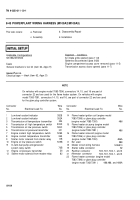
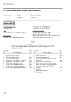
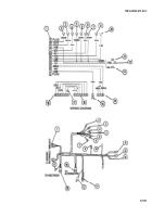
8-44 POWERPLANT WIRING HARNESS (M109A4/M109A5) — CONTINUED
a. Removal
1
2
3
4
5
6
7
8
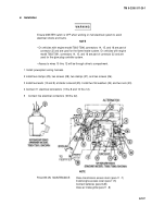
WARNIN G
Ensure MASTER switch is OFF when working on hull electrical system to avoid
electrical shocks and bums.
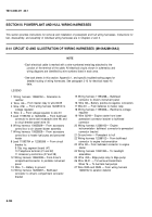
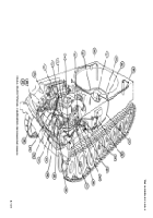
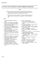
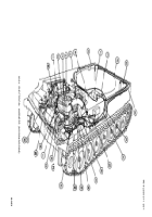
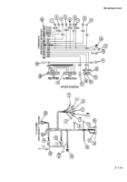
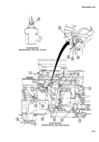
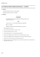
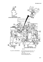
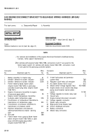
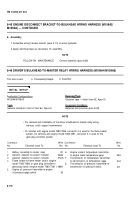
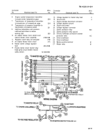
Disconnect driver’s bulkhead-to-master relay wiring harness (19) at engine disconnect bracket (20).
Remove four nuts (21), four Iockwashers (22), four washers (23), and four screws (24). Discard lockwashers.
Remove connector (1) from engine disconnect bracket (20).
Disconnect two electrical connectors (17 and 18).
NOTE
•
Access to wires 11, 12, and 13 will be through driver’s compartment.
Ž
Wire 15 is plugged.
Ž
Powerplant must be removed to remove starter lead (10) (para 4-5).
Disconnect 13 electrical connectors (2 thru 9 and 11 thru 16).
Remove nut (25) and flat washer (26). Remove lead (10) at starter solenoid (27).
Remove two screws (28), two washers (29), two nuts (30), two clamps (31 ), four screws (32), four Iockwashers
(33), and four clamps (34). Place four screws (32) back into engine. Discard Iockwashers.
Remove powerplant wiring harness.
b. Disassembly/Repair
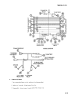
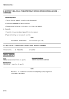
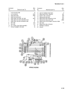
1 Remove electrical tape where necessary for disassembly.
2 Isolate and separate wiring harness branches.
3 Disassemble wiring branch (para 2-13) of wires to be replaced.
8-110
TM 9-2350-311-20-1
Back to Top

