TM-9-2350-311-20-1 - Page 914 of 1275
TM 9-2350-311-20-1
NOTE
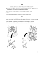
Speedometer adapter (19) has a keyed pin. During removal of adapter, remove and
store keyed pin until ready for installation. Speedometer will not work without pin.
8 Remove four screws (20), four lockwashers (21), and speedometer driveshaft adapter (19) with gasket (22)
from transmission at right universal joint. Discard lockwashers and gasket.
9 Remove tachometer driveshaft adapter (18) from engine, adjacent to alternator housing.
b. Installation
1 Install tachometer driveshaft adapter (18) into engine, adjacent to alternator housing.
NOTE
Be sure to install keyed pin (saved during removal) so that speedometer will function.
2 Install new gasket (22), speedometer driveshaft adapter (19), four new lockwashers (21), and four screws (20).
3 Install speedometer flexible driveshaft (10) to speedometer driveshaft adapter (19) at drive joint.
4 Install tachometer flexible driveshaft (9) to tachometer driveshaft adapter (18) at drive joint.
9-59
Back to Top

