TM-9-2350-311-20-1 - Page 911 of 1275
TM 9-2350-311 -20-1
9-17 WARNING LIGHT AND STOP LIGHT SWITCHES
This task covers:
Adjustment
General mechanic’s tool kit (item 64, Appx H)
Adjustment
1
2
3
4
5
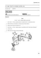
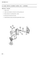
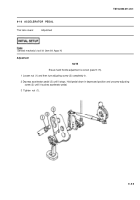
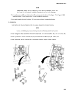
To adjust warning light switch, loosen two nuts (1) and move parking brake handle (2) out 0.375 in. (9.5 mm).
Adjust two nuts (1) until switch (3) touches arm (4). Tighten two nuts.
To adjust stop light switch, depress brake pedal (5) 0.75 in. (19.1 mm) and lock brakes.
Loosen socket head screws (6) and turn stop light actuator (7) until it touches stop light switch (8).
Tighten screws (6).
9-56
Back to Top

