TM-9-2350-311-20-1 - Page 907 of 1275
TM 9-2350-311-20-1
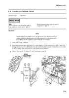
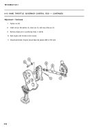
9-14 ENGINE THROTTLE GOVERNOR CONTROL ROD
This task covers:
Adjustment
General mechanic’s tool kit (item 64, A
PPX
H)
Adjustment
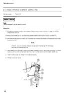
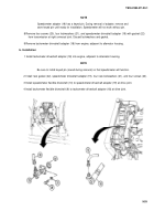
1 Fully depress accelerator pedal to move engine throttle governor control rod lever (1) away from driver’s
compartment bulkhead.
2 Remove quick-release pin (2), and disconnect engine throttle governor control rod (3) from Iever (1).
3 Push engine throttle governor control rod (3) towards rear of vehicle (accelerator still depressed) and loosen
control rod nut (4).
4
5
6
A 0.25-in. - (6.4-mm-) diameter dowel pin may be used. Fit will be tight. Pin fits through
lever and into bulkhead pilot hole.
Note whether pin (2) removed in step 2 can be easily installed in lever (1) and control rod end (5). If it cannot,
loosen nut (4) on control rod and twist rod end 1/2 turn at a time until pin can be installed. Tighten nut.
Install rod (3) and pin (2). Linkage is now adjusted properly.
Release accelerator pedal.
9-52
NOTE
Back to Top

