TM-9-2350-311-20-1 - Page 901 of 1275
TM 9-2350-311-20-1
9-11 ACCELERATOR, THROTTLE, AND ENGINE CONTROL GOVERNOR —
CONTINUED
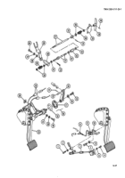
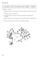
d. Installation
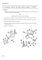
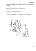
1 Install pedal and shaft assembly (48), mounting bracket (47), two flat washers (46), two lockwashers (45), two
screws (44), and spring (43) at support bracket.
NOTE
Replace inserts (32 and 33) only if threads are damaged.
2 Install throttle control assembly (40), new key washer (42), and screw (41). Install insert (33) if removed.
3 Install pin (38) and new cotter pin (37) at end of throttle control rod (39) to install in driver’s compartment.
4 Install bracket support assembly (36) at bulkhead.
5 Install three inserts (32) if necessary. Install three new lockwashers (35) and three screws (34) at bracket
support assembly (36).
6 Install lever (31) and pin (30).
9-46
Back to Top

