TM-9-2350-311-20-1 - Page 893 of 1275
9-10 SERVICE AND PARKING BRAKE LINKAGE — CONTINUED
e. Adjustment
1
2
3
4
5
6
7
8
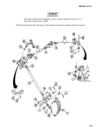
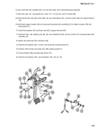
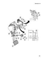
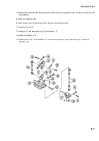
Release service brake. Check for slack in sprocket control chain (88). If no slack is present, go to step 2. If
slack is present, remove cotter pin (82) and clevis pin (83) from brake shaft lever (85). Discard cotter pin.
Loosen nut (76) and turn rod (78) clockwise to shorten. Replace clevis pin and check for slack again. If slack is
still present, repeat as above. If no slack is present, install new cotter pin and go to step 2.
Check to ensure alinement of brake apply shaft index mark with release point (89). If linkage alinement is
correct, go to step 3. If not alined, adjust length of rod (78) until they are alined.
After brake adjustment, loosen nut (90) on brake pedal lever stop screw (91). Adjust brake shaft lever stop
screw so that pedal has 0.75 in. (19.1 mm) free travel. Tighten nut.
Loosen parking brake bracket (28) by removing screws (4) and Iockwashers (5). Discard Iockwashers.
Unlock parking brake handle (26) (up position). Loosen two nuts (42) on forward brake control rod (92) and
rear brake control rod (93).
Turn connecting nut (43) in either direction until holes in parking brake bracket (28) aline with mating holes
(hidden), and with no pressure on bell crank (39).
Secure bracket (28) to hull with two screws (4) and two new Iockwashers (5). Tighten two nuts (42) on each of
control rods (92 and 93).
Depress brake pedal (51). Pull back on parking brake handle (26). Remove foot from pedal. Brake should stay
locked. To release parking brakes, lift up and in on parking brake handle; then depress and release brake
pedal.
9-38
TM9-2350-311-20-1
Back to Top

