TM-9-2350-311-20-1 - Page 890 of 1275
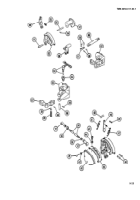
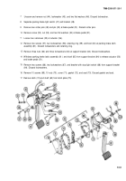
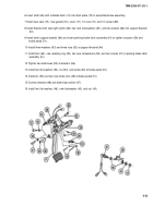
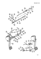
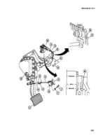
6 Insert shaft (65) with installed latch (74) into latch plate (75) to assemble brake assembly.
7 Install new seal (73), new gasket (72), cover (71), 10 nuts (70), and 10 screws (69).
8 Install bracket with stop light switch (68), two new Iockwashers (67), and two screws (66) into support bracket
(64).
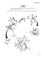
9 Install shaft support bracket (64) and insert parking brake latch assembly (61) to tighten actuator (56) and
brake pedal (51).
10 Install three washers (63) and three nuts (62) at support bracket (64).
11 Install boot (60), new retaining ring (59), two new Iockwashers (58), and two screws (57) at parking brake latch
assembly (61).
12 Tighten two setscrews (55) at actuator (56).
13 Install two flat washers (54), nut (53), and screw (52) at brake pedal (51).
14 Install pin (50) and two new cotter pins (49) at brake pedal (51).
15 Connect bracket (48) and brake light switch (47).
16 Install two flat washers (46), new Iockwasher (45), and nut (44).
9-35
TM9-2350-311-20-1
Back to Top

