TM-9-2350-311-20-1 - Page 886 of 1275
TM9-2350-311-20-1
6
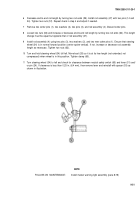
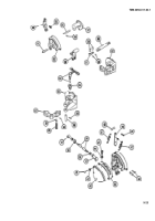
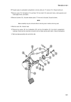
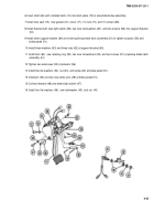
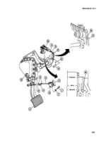
Through access to powerplant compartment, remove cotter pin (11 and pin (12). Discard cotter pin.
7
Remove screw (13), flat washer (14), and lever 15) from shaft. (For removal of clevis, chain sprocket, and
brake apply levers, see below.)
8 Remove Iockwire (16). Unscrew retainer plate (17) from end of bracket. Discard Iockwire.
NOTE
Brake assembly may be removed without removing seal or before removing seal.
9 Remove seal (18). Discard seal.
10 Remove four screws (19), four Iockwashers (20), and four flat washers (21) from driver’s compartment
bulkhead. Disconnect two electrical connectors (22) at brake warning light switch. Discard Iockwashers.
11 Remove brake assembly (23) and shims (24).
9-31
Back to Top

